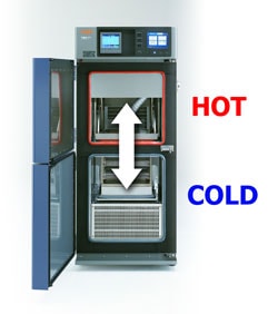
 Unfortunately many people use the same name to refer to different tests. Thermal shock is one of those. Let me elaborate:
Definitions:
1. Alternately dipping the product in hot and cold liquids. More precisely, this should be referred to “liquid-to-liquid thermal shock”.
2. Changing the air temperature as quickly as possible in a single chamber. This we would recommend calling “thermal cycling” or “stress screening” and isn’t truly thermal shock.
3. Moving the product from a hot to a cold chamber or other sudden change of the air temperature. This is “air-to-air thermal shock” or “two-zone thermal shock.”
***
Sometimes during transfer as described in 3, there is an intermediate step of exposure to room temperature. This is done to allow manual transfer of the product. This is called a “three-zone thermal shock”. Mil-Std 202F method 107G allows such a step, for example.
So, from the above list, you can see the variations in what people commonly call “thermal shock”. It should also be noted that some specifications call for “thermal cycling” which is actually “air-to-air thermal shock”.
With thermal shock tests, there are also several ways to define and measure the performance. Thermal shock tests focus on “recovery time”, or how long it takes to stabilize after the switch.
Recovery time can also be defined several ways:
1. Time it takes for the product to move from zone to zone. True name: “transfer time”
2. Time for the air temperature to recover in the new zone. This can be measured in the air stream before or after the test load. This can be called “upstream recovery time” or “downstream recovery time”.
3. Time for the physical product to recover, called “product recovery”. This time is dependent on where the sensor is placed on the load. Mil-Std 883 method 1010.7 defines their requirement as “worst-case” product recovery, which is for a sensor embedded in a sample buried among other samples.
***
Of course, some test specifications only make the confusion between thermal shock and thermal cycling worse. One example is Telcordia (Bellcore) GR-468 that states “Method 1010 of Mil-Std 883C with a minimum temperature ramp rate of 10C/min.” Many people assume that a cycling chamber that does 10°C/min. is sufficient, although the Mil-Std clearly defines the transfer time and recover time, which, if you have been paying attention a thermal shock test.
So when you are asked to do a thermal shock test, be sure that you have a clear definition of the requirements, otherwise it is easy to do incorrectly, or buy the wrong equipment.
 ESPEC North America, Inc. (Corporate office)

 Unfortunately many people use the same name to refer to different tests. Thermal shock is one of those. Let me elaborate: